Application Case 2—Hardware-Timed Simultaneously Updated I/O with Data Exchanges between Time-Critical and Non-Time-Critical Loops
Requirement
"My I/O needs to be hardware-timed. All output values need to simultaneously update at the arrival of the sample clock edge. I need to exchange data between my time-critical loop and my lower-priority processes."
Solution
- Use the Wait For Next Sample Clock VI (WFNSC) to verify that a new sample clock edge has not yet occurred.
- Place the communication code (usually real-time FIFOs) after the Wait For Next Sample Clock VI.
Advantages
- The current iteration's output samples are guaranteed to be aligned with the next iteration's input samples.
- NI-DAQmx returns an error if the Wait For Next Sample Clock VI does not start before the next sample clock edge occurs.
- I/O jitter is confined to the jitter of the hardware clock, which is on the order of a few nanoseconds.
- Hardware-timed counter input operations have no conversion period similar to that of multiplexed analog input. Therefore, you can place the real-time FIFO anywhere within the LabVIEW loop.
Restrictions
Read, process, and write operations are confined to the amount of time available between the moment the device starts acquiring data and the moment the next sample clock edge arrives.
Sample Application
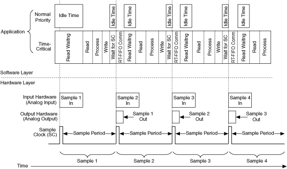
An example of this kind of application is an analog control loop that reads samples from a specific number of analog input channels, processes the data using a control algorithm (such as PID), and writes the new control values to the analog output channels. The application uses a real-time FIFO to stop the control loop based on a Boolean value provided by a lower-priority process. A similar approach can employ the use of real-time FIFOs to vary the PID parameters on the fly, or to transfer acquired and control output values to lower-priority processes for data logging and remote monitoring.
Sample Timing Diagram

Sample Implementation
- Wire the Wait For Next Sample Clock VI to one of the hardware-timed tasks. Use dataflow wiring to guarantee that the Wait For Next Sample Clock VI executes after the AO Write call.
- Use dataflow wiring to guarantee that the real-time FIFO operations execute after the Wait For Next Sample Clock VI executes.
- If the Wait For Next Sample Clock VI does not execute before the arrival of the next sample clock edge, it returns an error.
Sample Block Diagram

Notes
- Use only one Wait For Next Sample Clock VI within a LabVIEW loop. If you have multiple hardware-timed I/O tasks within the same LabVIEW loop, you can connect the Wait For Next Sample Clock VI to any one hardware-timed single-point task within that loop.
- If, when a cycle overflow occurs, you want to receive a warning rather than an error, set the DAQmx Real-Time»Convert Late Errors to Warnings property to True.
- Although you do not have to place the real-time FIFO code after the Wait For Next Sample Clock VI, it is highly recommended that you do so when dealing with multiple-channel analog input operations on multiplexed devices (such as E and M Series). Because the device can spend up to 50% of the sample period converting samples on the analog input channels, executing the FIFO code during this conversion period has the advantage of using up otherwise idle time.
- You can increase the Analog Input Conversion Rate manually through the DAQmx Timing Property Node. This reduces the total amount of time spent converting the requested number of samples. It is important to consider the minimum settling time specifications for the complete data acquisition system to avoid signal degradation and interference.


