Application Case 4—Hardware-Timed Counter Tasks
Requirement
"I want to use hardware-timed counter input operations to drive my control loop."
Solution
Use the Wait For Next Sample Clock VI to synchronize the counter operations with the counter's sample clock.
Advantages
- Counter tasks allow for flexible timing and event detection operations that can drive the software processing of the control loop. In other words, the control loop can have a dynamic clock rate.
- NI-DAQmx returns an error if the Wait For Next Sample Clock VI is not started before the next sample clock edge arrives.
Restrictions
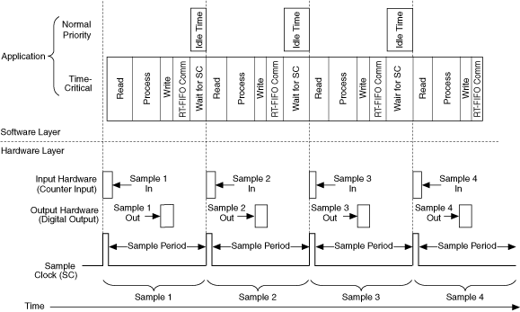
Read, process, and write operations are confined to the time available between the moment the device starts acquiring data and the moment the next sample clock edge arrives.
Sample Application
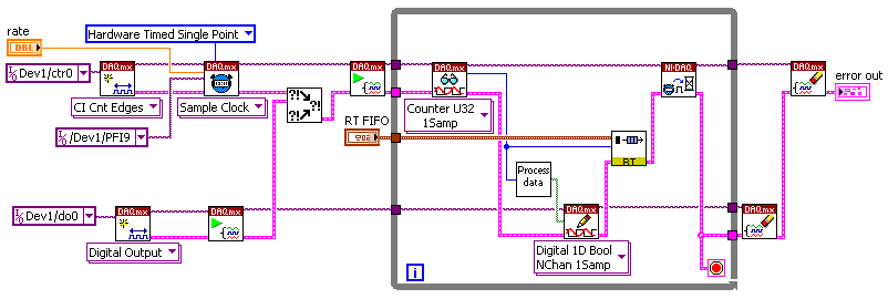
An example of this kind of application is a control loop that uses a counter input task, such as count edges, while controlling digital lines based on some predefined control logic. This sample application performs communication through the use of real-time FIFOs.
Sample Timing Diagram

Sample Implementation
- Wire the Wait For Next Sample Clock VI to the counter input task.
- If the Wait For Next Sample Clock VI does execute before the arrival of the next sample clock edge, it returns an error.
Sample Block Diagram

Sample Application 2
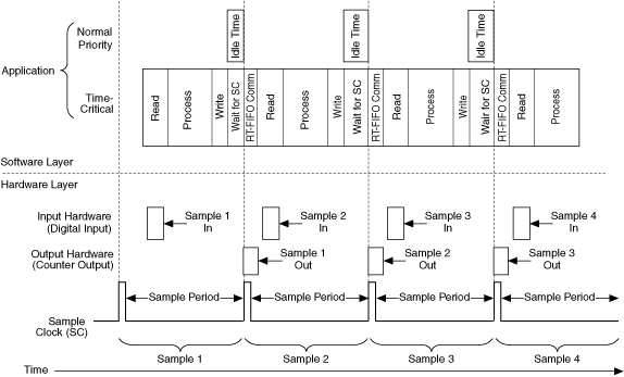
Another example application is a control loop that monitors discrete inputs and uses the values to update a counter output task, using pulse frequency mode to generate pulse-width modulation control signals. This example application performs communication through the use of real-time FIFOs.
Sample Timing Diagram

Sample Implementation
- Wire the Wait For Next Sample Clock VI to the counter output task.
- If the Wait For Next Sample Clock VI does not execute before the arrival of the next sample clock edge, it returns an error.
Sample Block Diagram

Notes
- Use only one Wait For Next Sample Clock VI within a LabVIEW loop. If you have multiple hardware-timed I/O tasks within the same LabVIEW loop, you can connect the Wait For Next Sample Clock VI to any one hardware-timed single point task within that loop.
- If, when a cycle overflow occurs, you want to receive a warning rather than an error, set the DAQmx Real-Time»Convert Late Errors to Warnings property to True.
- Hardware-timed counter operations have no conversion period similar to that of multiplexed analog input. Therefore, the real-time FIFO can be placed anywhere within the LabVIEW loop.
- NI-DAQmx provides a mechanism to recover after missing a sample clock edge when performing counter writes. If this write recovery mechanism is not successful, NI-DAQmx returns an error, and subsequent operations on that task are no longer hardware timed.
- The DAQmx Real-Time»Write Recovery Mode property allows you to choose between Wait For Interrupt or Polling mode for the recovery mechanism. Wait For Interrupt, which is the default, allows lower priority processes to execute while NI-DAQmx attempts to recover. Polling mode, on the other hand, allows for higher sampling rates.


